NEED OF RS232
Simple analog communication over the telephone wires to the typical USB cables for data exchange, we surely have come a long way in the field of communication. RS232 was the first milestone reached in this journey. It was a standard for electromechanical typewriters and modems for digital data exchange introduced in 1962 by the Radio Sector of EIA. It made the data exchange more reliable over analog channel. The standard defined voltage levels that made it immune to noise disturbances and reduced the error in data exchange.
As the technology was growing many electronic devices were being developed during this time like computers, printers, test instrument etc. There came a time where manufacturers felt the need to exchange information between these electronic devices. For example data exchange between a computer and a printer or two computers. But there was no standard or method to accomplish this task. RS232 was the only available standard at the time which was used for data exchange. So, they thought of adopting this standard in electronic devices for digital data exchange. But the standard was unable to fulfill the requirements as it was developed specifically for modem and teletypewriter. To overcome this problem, designers started implementing an RS232 interface compatible to their equipment's. Like a computer of HP will only be able to use HP peripheral devices. Because of this the market was flooded with different manufactures with their own standards for their devices. This led to the common problems like non-standard pin assignment of circuits on connectors, and incorrect or missing control signals. The lack of adherence to the standard produced a thriving industry of breakout boxes, patch boxes, test equipment's, books and other aids for the connection of dissimilar equipment's. So, to put an end to all theses disparities in equipment's, syndicate of manufacturers built a transmitter that supplied +5V and -5v and labeled them as “RS-232” compatible and they are same till date. The standard has been revised many times after the initial one and updated by Electronic industries association. The name of standard was also changed from RS232 to EIA232. The Electronic Industries Association published three modifications, the most recent being EIA232F introduced in 1997.
What is RS232 - "RECOMMENDED STANDARD 232"
RS-232 is a standard communication protocol for linking computer and its peripheral devices to allow serial data exchange. In simple terms RS232 defines the voltage for the path used for data exchange between the devices. It specifies common voltage and signal level, common pin wire configuration and minimum, amount of control signals. As mentioned above this standard was designed with specification for electro mechanically teletypewriter and modem system and did not define elements such as character encoding, framing of characters, error detection protocols etc that are essential features when data transfer takes place between a computer and a printer. Without which it could not be adopted to transfer data between a computer and a printer. To overcome this problem a single integrated circuit called as UART known as universal asynchronous receiver/transmitter is used in conjunction with RS232.

It is clear from this figure that UART, line drivers and RS232 are three separate parts in the system each having its own characteristic features. UART and line drivers are the parts in RS232 to enhance quality of system during serial data exchange.
A standard definition was given by EIA to define RS232 as “an interface between Data terminal equipment and Data communication equipment”. A typical RS232 system is shown below.

DCE-A DCE stands for data communication equipment's. It sits between the DTE and data transmission circuit for example modem. A DCE device uses a female connector which has holes on the surface to hold male connector.
A minimum of three signals are required for communication between a DTE and a DCE devices. These signals are a transmission line, a reception line and ground. These two devices communicate with each other by handshaking. It allows a DTE and a DCE device system to acknowledge each other before sending the data.
Handshaking is a process in which a DTE device sends a signal to a DCE device to establish a connection between the devices before the actual transfer of data. It sets the parameters of communication channel established between two equipment's before normal communication over the channel begins. It follows physical establishment of the channel and precedes normal information transfer. Handshaking makes it possible to connect relatively heterogeneous systems or equipment over a communication channel without the need for human intervention to set parameters. This same concept is used in RS232 to allow two devices communicate with each other before the actual exchange of information.
All these terms put together gives a complete picture of a RS232 system starting from DTE to DCE with UART, line drivers and RS232 as conjunction between them.
Using the USART of AVR Microcontrollers.
Welcome to the third part of my RS232 serial communication tutorial. Till now we saw the basics of RS232 communication and made our level converter. Now its time to understand the USART of AVR microcontroller and write the code to initialize the USART and use it to send and receive data.
Like many microcontrollers AVR also has a dedicated hardware for serial communication this part is called the USART - Universal Synchronous Asynchronous Receiver Transmitter. This special hardware make your life as programmer easier. You just have to supply the data you need to transmit and it will do the rest. As you saw serial communication occurs at standard speeds of 9600,19200 bps etc and this speeds are slow compared to the AVR CPUs speed. The advantage of hardware USART is that you just need to write the data to one of the registers of USART and your done, you are free to do other things while USART is transmitting the byte.
Also the USART automatically senses the start of transmission of RX line and then inputs the whole byte and when it has the byte it informs you(CPU) to read that data from one of its registers.
The USART of AVR is very versatile and can be setup for various different mode as required by your application. In this tutorial I will show you how to configure the USART in a most common configuration and simply send and receive data. Later on I will give you my library of USART that can further ease you work. It will be little complicated (but more useful) as it will have a FIFO buffer and will use interrupt to buffer incoming data so that you are free to anything in your main() code and read the data only when you need. All data is stored into a nice FIFO(first in first out queue) in the RAM by the ISR.
USART of AVR Microcontrollers.
The USART of the AVR is connected to the CPU by the following six registers.
- UDR - USART Data Register : Actually this is not one but two register but when you read it you will get the data stored in receive buffer and when you write data to it goes into the transmitters buffer. This important to remember it.
- UCSRA - USART Control and status Register A : As the name suggests it is used to configure the USART and it also stores some status about the USART. There are two more of this kind the UCSRB and UCSRC.
- UBRRH and UBRRH : This is the USART Baud rate register, it is 16BIT wide so UBRRH is the High Byte and UBRRL is Low byte. But as we are using C language it is directly available as UBRR and compiler manages the 16BIT access.
So the connection of AVR and its internal USART can be visualized as follows.
Fig- AVR USART registers.
Registers Explained
In order to write programs that uses the USART you need to understand what each register's importance. The scheme behind using the AVR USART is same as with any other internal peripheral (say ADC). So if you are new to this topic please see this tutorial, it shows you the basic idea of using peripherals.
I am not going to repeat what is already there in the datasheets, I will just tell about what is required for a quick startup. The datasheets of AVR provides you with all the details of every bit of every register so please refer to it for detailed info. Note bit names with RED background are of our interest here.
UDR: Explained above.
UCSRA: USART Control and Status Register A
*****************************************
Bit No
|
7
|
6
|
5
|
4
|
3
|
2
|
1
|
0
|
Name
|
RXC
|
TXC
|
UDRE
|
FE
|
DOR
|
PE
|
U2X
|
MPCM
|
Initial Val
|
0
|
0
|
1
|
0
|
0
|
0
|
0
|
0
|
RXC this bit is set when the USART has completed receiving a byte from the host (may be your PC) and the program should read it from UDR
TXC This bit is set (1) when the USART has completed transmitting a byte to the host and your program can write new data to USART via UDR
UCSRB: USART Control and Status Register B
*****************************************
Bit No
|
7
|
6
|
5
|
4
|
3
|
2
|
1
|
0
|
Name
|
RXCIE
|
TXCIE
|
UDRIE
|
RXEN
|
TXEN
|
UCSZ2
|
RXB8
|
TXB8
|
Initial Val
|
0
|
0
|
0
|
0
|
0
|
0
|
0
|
0
|
RXCIE: Receive Complete Interrupt Enable - When this bit is written one the the associated interrupt is enabled.
TXCIE: Transmit Complete Interrupt Enable - When this bit is written one the the associated interrupt is enabled.
RXEN: Receiver Enable - When you write this bit to 1 the USART receiver is enabled. The normal port functionality of RX pin will be overridden. So you see that the associated I/O pin now switch to its secondary function,i.e. RX for USART.
TXEN: Transmitter Enable - As the name says!
UCSZ2: USART Character Size - Discussed later.
For our first example we won't be using interrupts so we set UCSRB as follows
UCSRB=(1<<RXEN)|(1<<TXEN);
UCSRC: USART Control And Status Register C
*****************************************
Bit No
|
7
|
6
|
5
|
4
|
3
|
2
|
1
|
0
|
Name
|
URSEL
|
UMSEL
|
UPM1
|
UPM0
|
USBS
|
UCSZ1
|
UCSZ0
|
UCPOL
|
Initial Val
|
0
|
0
|
0
|
0
|
0
|
0
|
0
|
0
|
IMPORTANT : The UCSRC and the UBRRH (discussed below) register shares same address so to determine which register user want to write is decided with the 7th(last) bit of data if its 1 then the data is written to UCSRC else it goes to UBRRH. This seventh bit is called the
URSEL: USART register select.
UMSEL: USART Mode Select - This bit selects between asynchronous and synchronous mode. As asynchronous mode is more popular with USART we will be using that.
UMSEL
|
Mode
|
0
|
Asynchronous
|
1
|
Synchronous
|
USBS: USART Stop Bit Select - This bit selects the number of stop bits in the data transfer.
USBS
|
Stop Bit(s)
|
0
|
1 BIT
|
1
|
2 BIT
|
UCSZ: USART Character size - These three bits (one in the UCSRB) selects the number of bits of data that is transmited in each frame. Normally the unit of data in MCU is 8BIT (C type "char") and this is most widely used so we will go for this. Otherwise you can select 5,6,7,8 or 9 bit frames!
UCSZ2
|
UCSZ1
|
UCSZ0
|
Character Size
|
0
|
0
|
0
|
5Bit
|
0
|
0
|
1
|
6Bit
|
0
|
1
|
0
|
7Bit
|
0
|
1
|
1
|
8Bit
|
1
|
0
|
0
|
Reserved
|
1
|
0
|
1
|
Reserved
|
1
|
1
|
0
|
Reserved
|
1
|
1
|
1
|
9Bit
|
So we set UCSRC as follows
UCSRC=(1<<URSEL)|(3<<UCSZ0);
UBRR: USART Baud Rate Register:
*********************************
This is the USART Baud rate register, it is 16BIT wide so UBRRH is the High Byte and UBRRL is Low byte. But as we are using C language it is directly available as UBRR and compiler manages the 16BIT access. This register is used by the USART to generate the data transmission at specified speed (say 9600Bps). To know about baud rate see the previous tutorial. UBRR value is calculated according to following formula.

Initialization of USART
Before using the USART it must be initialized properly according to need. Having the knowledge of RS232 communication and Internal USART of AVR you can do that easily. We will create a function that will initialize the USART for us.
#include <avr/io.h>
#include <inttypes.h>

void USARTInit(uint16_t ubrr_value)
{

   //Set Baud rate
   UBRR= ubrr_value;

   /*Set Frame Format


   >> Asynchronous mode
   >> No Parity
   >> 1 StopBit
   >> char size 8

   */

   UCSRC=(1<<URSEL)|(3<<UCSZ0);


   //Enable The receiver and transmitter
   UCSRB=(1<<RXEN)|(1<<TXEN);


}
Now we have a function that initializes the USART with a given UBRR value.
Reading and Writing Data :
Till now we have seen the basics of RS232 communication, the function of level converter and the internal USART of AVR micro. After understanding the USART of AVR we have also written a easy to use function to initialize the USART. That was the first step to use RS232. Now we will see how we can actually send/receive data via rs232. As this tutorial is intended for those who are never used USART we will keep the things simple so as to just concentrate on the "USART" part. Of course after you are comfortable with usart you can make it more usable my using interrupt driven mechanism rather than "polling" the usart.
So lets get started! In this section we will make two functions :-
- USARTReadChar() : To read the data (char) from the USART buffer.
- USARTWriteChar(): To write a given data (char) to the USART.
This two functions will demonstrate the use of USART in the most basic and simplest way. After that you can easily write functions that can write strings to USART.
Reading From The USART : USARTReadChar() Function.
This function will help you read data from the USART. For example if you use your PC to send data to your micro the data is automatically received by the USART of AVR and put in a buffer and bit in a register (UCSRA) is also set to indicate that data is available in buffer. Its now your duty to read this data from the register and process it, otherwise if new data comes in the previous one will be lost. So the funda is that wait until the RXC bit (bit no 7) in UCSRA is SET and then read the UDR register of the USART.
char USARTReadChar()
{
   //Wait untill a data is available

   while(!(UCSRA & (1<<RXC)))
   {
      //Do nothing
   }

   //Now USART has got data from host
   //and is available is buffer

   return UDR;
}
Writing to USART : USARTWriteChar()
This function will help you write a given character data to the USART. Actually we write to the buffer of USART and the rest is done by USART, that means it automatically sends the data over RS232 line. One thing we need to keep in mind is that before writing to USART buffer we must first check that the buffer is free or not. It its not we simply wait until it is free. If its not free it means that USART is still busy sending some other data and once it finishes it will take the new data from buffer and start sending it.
Please not that the data held in the buffer is not the current data which the USART is busy sending. USART reads data from the buffer to its shift register which it starts sending and thus the buffer is free for your data. Every time the USART gets it data from buffer and thus making it empty it notifies this to the CPU by telling "USART Data Register Ran Empty" (UDRE) . It does so by setting a bit (UDRE bit no 5) in UCSRA register.
So in our function we first wait until this bit is set (by the USART ), once this is set we are sure that buffer is empty and we can write new data to it.
void USARTWriteChar(char data)
{
   //Wait until the transmitter is ready

   while(!(UCSRA & (1<<UDRE)))
   {
      //Do nothing
   }

   //Now write the data to USART buffer

   UDR=data;
}
Note: Actually their are two separate buffers, one for transmitter and one for receiver. But they share common address. The trick is that all "writes" goes to the Transmitter's buffer while any "read" you performs comes from the receiver's buffer.
That means if we read UDR we are reading from receivers buffer and when we are writing to UDR we are writing to transmitters buffer.
UDR=some_data; //Goes to transmitter
some_data=UDR; //Data comes from receiver
(See the full description of USART registers)
Sample program to use AVR USART
The following program makes use of the two functions we developed. This program simply waits for data to become available and then echoes it back via transmitter but with little modification. For example if you send "A" to it, it will send you back "[A]" that is input data but surrounded by square bracket. This program is enough to test the USART yet easy to understand.
/*

A simple program to demonstrate the use of USART of AVR micro

*************************************************************
Hardware:
   ATmega8 @ 16MHz

   Suitable level converter on RX/TX line
   Connected to PC via RS232
   PC Software :  Hyper terminal @ 9600 baud
               No Parity,1 Stop Bit,
               Flow Control = NONE

*/

#include <avr/io.h>
#include <inttypes.h>

//This function is used to initialize the USART
//at a given UBRR value
void USARTInit(uint16_t ubrr_value)
{

   //Set Baud rate

   UBRRL = ubrr_value;
   UBRRH = (ubrr_value>>8);

   /*Set Frame Format

   >> Asynchronous mode
   >> No Parity
   >> 1 StopBit

   >> char size 8

   */

   UCSRC=(1<<URSEL)|(3<<UCSZ0);


   //Enable The receiver and transmitter

   UCSRB=(1<<RXEN)|(1<<TXEN);


}


//This function is used to read the available data
//from USART. This function will wait untill data is
//available.
char USARTReadChar()
{
   //Wait untill a data is available

   while(!(UCSRA & (1<<RXC)))
   {
      //Do nothing
   }

   //Now USART has got data from host
   //and is available is buffer

   return UDR;
}


//This fuction writes the given "data" to
//the USART which then transmit it via TX line
void USARTWriteChar(char data)
{
   //Wait untill the transmitter is ready

   while(!(UCSRA & (1<<UDRE)))
   {
      //Do nothing
   }

   //Now write the data to USART buffer

   UDR=data;
}

void main()
{
   //This DEMO program will demonstrate the use of simple

   //function for using the USART for data communication

   //Varriable Declaration
   char data;

   /*First Initialize the USART with baud rate = 9600bps

   for Baud rate = 9600bps

   UBRR value = 103

   */

   USARTInit(103);    //UBRR = 103

   //Loop forever

   while(1)
   {
      //Read data
      data=USARTReadChar();

      /* Now send the same data but but surround it in
      square bracket. For example if user sent 'a' our
      system will echo back '[a]'.

      */

      USARTWriteChar('[');
      USARTWriteChar(data);
      USARTWriteChar(']');

   }
}
Download the code here.
Running the USART Demo
You can run the above program in a ATmega8, ATmega16, ATmega32 cpu running at 16MHz without any modification. If you are using different clock frequency you have to change the UBRR value that we are passing to USARTInit() function. See previous tutorial for calculating UBRR value. AVR running the USART demo program can be interface to PC using following three ways.
Connect to a Physical COM Port.
If you are lucky and own a really old PC then you may find a Physical COM port on your PC's back. It is a 9 pin D type male connector. In this case you have to make a RS232 to TTL converter and connect the MCU to COM port via it.Connect to a Virtual COM Port.
Those who are not so lucky may buy a Virtual COM port. Again in this case too you need to built a RS232 to TTL converter and connect the MCU to COM port via it.
- Prolific USB-to-Serial if you are using Bafo USB to Serial Converter.
- Silicon Labs CP210x if you are using CP2102 chip.
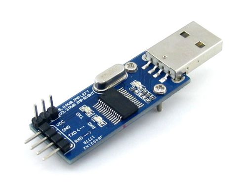
Connect via Chip PL2303
PL2303 is yet another low cost chip for USB to serial (TTL Level) conversion. We also have a complete board for it too !
Finding the COM port number of Serial Port
A PC can have several COM ports, each may have some peripheral connected to it like a Modem. Serial Ports on PC are numbered like COM1, COM2 ... COMn etc. You first need to figure out in which COM port you have connected the AVR. Only after you have a correct COM port number you can communicate with the AVR using tools such as Hyperterminal. The steps below shows how to get COM port number in case of Virtual COM Ports.
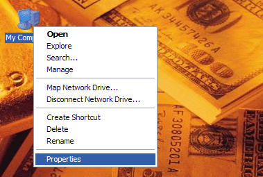
Right Click on "My Computer" icon in Windows Desktop.
My Computer Icon on Windows Desktop |
Select "Properties"
 |
System Context Menu |
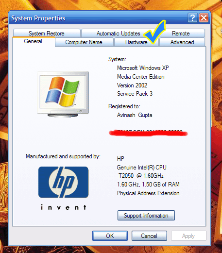
The System Properties will open up. Go to the "Hardware" Tab.
 |
System Properties. |
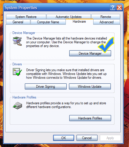
In Hardware tab select "Device Manager" button. It will open up device manager.
 |
Open Device Manager |
In Device Manager Find the Node "Ports (COM & LPT)"
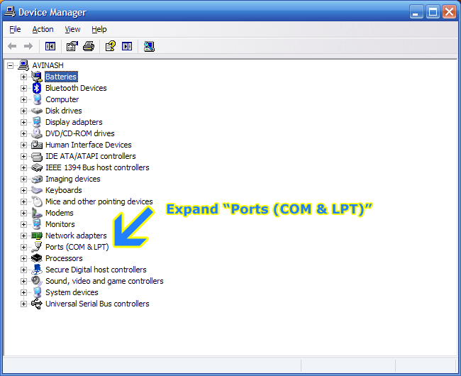 |
Expand the PORT node in Device Manager |
Depending on whether you are using a "USB to Serial Converter" or "CP2102 USB/USART Bridge Module" you have to find the port with following name.
Note down the COM port number next to the port name. You need to open this Port in Hyperterminal.
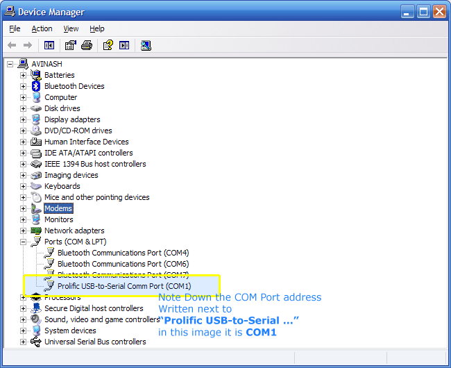 |
COM Port Number |
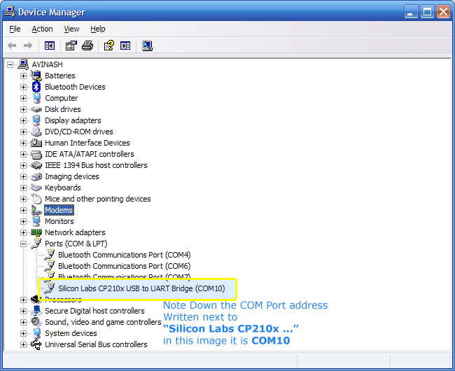 |
COM Port Number |


No comments:
Post a Comment